
Image Formation by Plane and Spherical Mirrors
Purpose
-
•To become familiar with the nature of the images formed by plane and spherical mirrors.
-
•To learn to distinguish between real and virtual images.
-
•To discover the relationships among object position, image position, focal length, magnification, and the radius of curvature of plane, converging, and diverging mirrors.
-
•To become familiar with sign conventions and how and why they're used.
Equipment
- Virtual Optical Bench
- Pencil
Simulation and Tools
Open the Virtual Optical Bench simulation to do this lab.Explore the Apparatus/Theory
Open the Virtual Optical Bench simulation.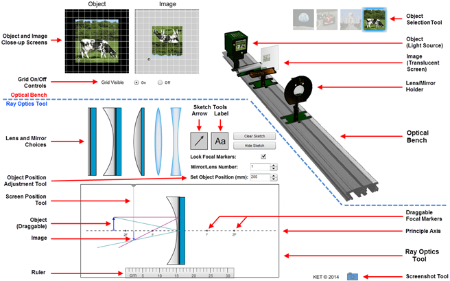
Figure 1: Optical Bench Apparatus

Figure 2: Object Arrow

Figure 3: Screen Position Tool
Procedure
Please print the worksheet for this lab. You will need this sheet to record your data.
I. Plane Mirrors; Virtual and Real Images
We're going to look at the behaviors of our three mirrors to learn the nature of the images they form as well as the geometry behind the image formation. Then we'll look at the algebraic descriptions of this geometry. We'll start with the plane mirror. Drag the plane mirror in place on the Ray Optics Tool. It should look something like Figure 4 minus a few added details.
The law of reflection states that when a ray of light reflects from a mirror the angle of incidence equals the angle of reflection.
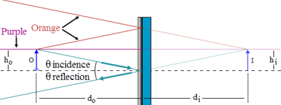
Figure 4: Image Formation by a Plane Mirror
1
As you drag the object toward the mirror, picture the equivalent activity of walking toward a bathroom or dressing room mirror. If you walked toward the mirror at 2 m/s, at what speed is your image moving toward the mirror?
2
At what speed is your image moving toward you? Remember, you're moving too.
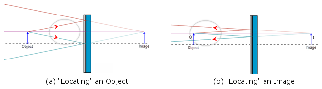
Figure 5: "Locating" an Object and an Image
Figure 6: Seeing an Image Without Using a Screen
Real vs. Virtual Images:
For real images, the light passes through the image and then diverges. We can put a screen at the location of the image and see it displayed there. Or we can allow the light diverging from the image to pass into our eyes which can then form an image (of an image) on our retinas. For virtual images the light only appears to diverge from the image. The light doesn't actually pass through the image. And as a result a virtual image can never be displayed on a screen.
For real images, the light passes through the image and then diverges. We can put a screen at the location of the image and see it displayed there. Or we can allow the light diverging from the image to pass into our eyes which can then form an image (of an image) on our retinas. For virtual images the light only appears to diverge from the image. The light doesn't actually pass through the image. And as a result a virtual image can never be displayed on a screen.
The Nature of an Image
Categorizing an image as real or virtual is a part of the process of determining the nature of an image. The nature of an image is determined based on three criteria.
To state the nature of the image you'll pick one from each of the following.
-
aIs the image real or virtual?
-
bIs the image reduced in size, the same size, or enlarged in size relative to the object.
-
cIs the image upright or inverted relative to the object?
3
Record the nature of the image formed by a plane mirror. Choose one for each category.
-
aReal or virtual? (real, virtual, no image)
-
bSize? (reduced, same size, enlarged)
-
cOrientation? (upright, inverted)
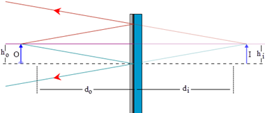
Figure 7: Object, Image Size, and Position for a Plane Mirror
II. Concave (Converging) Mirrors
1
The second mirror choice, which you've already seen, is a concave mirror. Drag it onto the Ray Optics Tool and then drag the object until the screen looks similar to Figure 8.
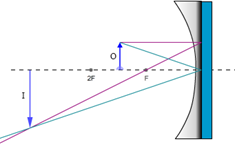
Figure 8: The Concave (Converging) Mirror
2
Both the object and the image are on the left side of the mirror. Drag the Screen Position Tool all the way to the right. Now start dragging it slowly to the left and watch the screen on the Optical Bench. Drag it just "through" the mirror and stop.
3
Notice what happened on the Image Close-up Screen at the top left of the lab screen. There's something fuzzy there. That's a very poor image of a cow. The problem is that it's not focused because the screen isn't where the image is located. Drag it a little more and you'll see the image begin to clear up both on the close-up screen and on the Optical Bench screen. Adjust the screen position until the image is well focused. Use the close-up screen to make these determinations.
4
What is the nature of this particular image? Check one for each category.
-
aReal or virtual? (real, virtual, no image)
-
bSize? (reduced, same size, enlarged)
-
cOrientation? (upright, inverted)
5
Dentists use mirrors to clearly see what they're doing when they're working on your teeth. Would you want your dentist to use a mirror system arranged like the one on your screen now? What would be the advantage of this arrangement? What would be the disadvantage? Look at the Object and Image Close-up Screens.
A. Focal Length, f, Object Distance, do, and Image Distance, di
The nature of the images formed by a concave mirror is not as neat and tidy as what we found with plane mirrors. The nature of the image and its location depend on the particular curvature of the mirror and the location of the object relative to the mirror. As shown in Figure 9a, the object distance, do, is the distance from the center of the reflective surface of the mirror out to the object, O. Similarly, the image, I, is located a distance di from the center of the reflective surface of the mirror. (Just as with plane mirrors we draw the rays and make our distance measurements as if they reflect off the back surface of the mirror.)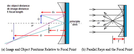
Figure 9: Image Formation by a Concave (Converging) Mirror
The focal length, f, is the distance along the principle axis from the focus to the center of the mirror.
1
We can find this experimentally with our Ray Optics Tool. Using the Object Position Adjustment Tool, (Set Object Position), adjust the object position to 120 mm. Notice that the incident rays, the two rays leaving the tip of the object arrow, are maybe 20° apart. The reflected rays, the two rays reflecting off the mirror, cross below the axis near the left end of the axis.
2
Click the "up" arrow on the Object Position Adjustment Tool tool until the object is at 280 mm. As you do this, notice how the angle between the incident rays becomes increasingly smaller and that the point where the reflected rays cross gets increasingly closer to the mirror and to the axis.
3
Repeat the preceding steps until you're clear on that.
4
Now start clicking the "up" arrow on the Object Position Adjustment Tool for a while and watch the two pairs of rays. Stop at about 1 m.
5
What did you observe about the trend in the angle between the two incident rays? That is, what is the angle between them approaching?
6
Reduce the object distance back to 120 mm and notice where the reflected rays cross at the tip of the Image Arrow.
7
Begin slowly clicking to gradually increase the object distance and observe how this crossing point moves.
8
As you increase the object distance, the incident rays continued to get closer to parallel. What's happening to the reflected rays? Where does their crossing point appear to be heading? Click and hold the object position tool until the object position reaches 3 m. Zoom in a couple of times for a close-up look.
9
What you've observed is the behavior of a concave spherical mirror. Rays parallel to the principle axis of a concave spherical mirror reflect and pass through the focal point as in Figure 9b. While you're zoomed in, grab the ruler and measure the focal length, f, of the mirror #1 mirror. Measure from the back of the mirror where it's attached to the bluish mounting surface, out to the focal point, F. It should be 7.5 cm. You can now right-click and select "show all" or "100%" to return to a normal magnification of the apparatus.
10
Click through the five mirror numbers and notice how the curvature of the mirror determines the focal length.
From here on you'll work with one of these mirrors that has been selected for you. You'll load that mirror by setting the Mirror/Lens Number to an integer from 2 through 5. These are not focal length values, just numbers identifying four different mirrors. Each focal length is a whole number multiple of 5 mm (4.0 cm, 6.5 cm, etc.).
11
Find the mirror number selected for you in WebAssign and select the matching mirror in the apparatus.
12
Using the techniques you used with mirror #1, measure and record your mirror's focal length.
13
Using your focal length value and the ruler, drag the F and 2F icons on the left side of the mirror to their proper places on the Ray Optics Tool. You won't need the other pair for now. Use the "Lock Focal Markers" check box to lock them in place.
B. Images Formed by a Concave Mirror
With our plane mirror, we found that the image and object are always equidistant from the mirror and that the nature of the image is that it's always upright, virtual, and the same size as the object. We'd like to be able to determine all the same information about images formed by concave and convex mirrors. We'll develop methods for determining this information geometrically with drawings and algebraically with equations based on the geometry. With concave mirrors, there are a number of different outcomes all depending on the relative values of the focal length and the object distance. They're different in that the nature of the image is different for each. This is important if you want an enlarged (relative to the object) image, a reduced image, etc., for a given situation. Although there are several outcomes, actually five, there is a logical pattern. We specify these as cases I–V. Yes, you do need to know these cases and be able to draw them! Case I: Object distance, do > 2f (do > R) For case I, the object is at any distance greater than two times the focal length from the mirror. That is, the object is beyond the 2F point. Drag the object back and forth between 2F and the left end of the principle axis to see its range of motion. Also notice the range of motion of the image.1
Move the object to about half-way between the 2F point and the left end of the axis. You'll see that the image is formed between the focal point, F, and 2F points.
2
Adjust the Screen Position Tool until you get a sharp image on the screens.
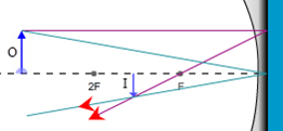
Figure 10: Eyes Locating a Real Image
Ray 1. The magenta, parallel ray goes from the tip of the object, parallel to the principle axis, and then reflects back through the focal point.
Ray 2. The green, focal ray goes from the tip of the object, through the focal point, and then back parallel to the principle axis. Note that the mirror in Figure 11 should have a smaller radius of curvature—less flat—to produce this ray since the ray should travel along a radius. But adjusting the mirror shape to match different focal lengths is tricky. So we just use one standard mirror for all cases. Sorry.
Ray 3. The orange, chief ray goes through the center of curvature, C, (at 2F) and then reflects back through C.
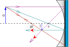
Figure 11: Three Rays Used in Locating Images with a Concave Mirror
3
Take a Screenshot of the Ray Optics Tool. Just include the object, image, and mirror. Save the image as "mirrors_case_I.png", and upload it.
4
The figure provided in Sketch 1 contains a mirror and principle axis with the F and 2F points labeled. To this figure add the object, image, and two rays to locate the image. You have three rays to choose from as described and illustrated in Figure 11. Use Ray 1 and either Ray 2 or Ray 3. So your diagram will look just like Figure 11, but with one fewer rays.
Sketch 1: Case I d0 > 2f
5
How about the nature of the image for case I? Check one for each category.
-
aReal or virtual? (real, virtual, no image)
-
bSize? (reduced, same size, enlarged)
-
cOrientation? (upright, inverted)
6
We want a reminder of how the object and image compared in size and orientation. The cow used as our object will never change. (Don't feed it during the lab.) There is an enlarged image of it at the top left of the screen with the corresponding image next to it. Take a Screenshot of the pair, save it as "mirrors_caseI_cows.png", and upload it.
7
In case I, the object can be anywhere beyond a distance of 2f from the mirror. That's a lot of territory. But it's a specific range of territory—everywhere beyond do = 2f.
The image also has a specific range of positions. The image distance, di, is the distance from the image to the center of the mirror. Drag the object back and forth, keeping outside the 2F point. How would you define the possible locations for the image?
1
Drag the object to the 2F point. (You can also use the cursor keys after clicking on the object.)
2
Adjust the Screen Position Tool until you get a sharp image on the screens.
3
Take a Screenshot of the Ray Optics Tool. Just include the object, image, and mirror. Save the image as "mirrors_case_II.png", and upload it.
4
In Sketch 2, create your own ray diagram as you did with case I. Be sure to include a pair of eyes at the end of your two rays.

Sketch 2: Case II d0 = 2f
5
How about the nature of the image for case II? Check one for each category.
-
aReal or virtual? (real, virtual, no image)
-
bSize? (reduced, same size, enlarged)
-
cOrientation? (upright, inverted)
6
Take a Screenshot of the object and image displays at the top left of the screen, save it as "mirrors_caseII_cows.png", and upload it.
7
In case I, the object could be anywhere beyond a distance of 2f from the mirror. In case II, the object has no room to roam. Likewise the image has a fixed position. How would you define the possible locations for the image?
1
Drag the object to about halfway between the F and 2F points. (You can also use the cursor keys.)
2
Adjust the Screen Position Tool until you get a sharp image on the screens.
3
Take a Screenshot of the Ray Optics Tool. Just include the object, image, and mirror. Save the image as "mirrors_case_III.png", and upload it.
4
In Sketch 3, create your ray diagram. Be sure to include a pair of eyes at the end of your two rays.
Sketch 3: Case III f < do < 2f
5
How about the nature of the image for case III? Check one for each category.
-
aReal or virtual? (real, virtual, no image)
-
bSize? (reduced, same size, enlarged)
-
cOrientation? (upright, inverted)
6
Take a Screenshot of the object and image displays at the top left of the screen, save it as "mirrors_caseIII_cows.png", and upload it.
7
In case I, the object could be anywhere beyond a distance of 2f from the mirror and the image was confined between F and 2F. In case III, the object again has a range of possible positions. How would you define the possible locations for the image?
1
Starting with the object at the 2F point, drag it slowly toward the focal point, F. Actually the cursor keys are better here. Notice how the rays reflected from the mirror behave. Keep moving until the object reaches the focal point. Then continue until it's about half-way between F and the mirror.
Before the object reaches the focal point the reflected rays are converging to the left of the mirror. As you get closer, they converge farther to the left and as a result the image is formed farther to the left.
2
After the object passes through F, where do the rays converge?
3
Drag the object back and forth through the focal point. What can you say about what must be happening to the reflected rays when the object is exactly at F?
4
Given that the (tip of) the image is formed where the reflected rays intersect, what can you say about the image?
5
Take a Screenshot of the relevant section of the Ray Optics Tool. Save the image as "mirrors_case_IV.png", and upload it.
6
In the figure provided, create your ray diagram. Be sure to include a pair of eyes at the end of your two rays.

Sketch 4: Case IV d0 = f
7
How about the nature of the image for case IV?
8
Take a Screenshot of the object and image displays at the top left of the screen, save it as "mirrors_caseIV_cows.png", and upload it.
1
Drag the object to about halfway between the F and the mirror. (Or use the cursor keys.) You can only get so close.
2
Adjust the Screen Position Tool until you get a sharp image on the screens. Hmm. That doesn't work so well. There is an image and you can move the screen to that point, but the image doesn't show up on the screens. You should be able to use what you've learned so far to make a clear statement about why you don't see an image on any screens. It will help to look at the geometry that produced your previous images. You might want to go back to your work with plane mirrors for insight. This is why you're asked to draw the eyes on all these figures. Discuss these three crucial points:
3
Take a Screenshot of the relevant section of the Ray Optics Tool. Save the image as "mirrors_case_V.png", and upload it.
4
In the figure provided in Sketch 5, create your ray diagram. Be sure to include a pair of eyes at the end of your two rays.
Sketch 5: Case V d0 < f
5
How about the nature of the image for case V? Check one for each category.
-
aReal or virtual? (real, virtual, no image)
-
bSize? (reduced, same size, enlarged)
-
cOrientation? (upright, inverted)
6
Take a Screenshot of the enlarged object and image displays at the top left of the screen, save it as "mirrors_caseV_cows.png", and upload it.
7
In cases I and III, the object could travel between infinity and 2F, and 2F and F respectively. The image locations were the reverse of this. In case V, the object again has a range of travel, this time between F and the mirror. How would you define the possible locations for the image?
III. Convex (Diverging) Mirrors
And now for something completely different. Switch to the convex, diverging mirror. Use the same mirror number as before. It will have the same focal length as the converging mirror, but as you'll see later, the sign will be negative.
1
Using your focal length value and the ruler, drag the F and 2F icons on the right side of the mirror to their proper places on the Ray Optics Tool. You won't need the left pair for this type of mirror. Use the "Lock Focal Markers" check box to lock them in place.
Converge means to come together. Rays parallel to the principle axis of converging devices bend light toward the focal point as shown in Figure 12a (repeat of Figure 9b).
Diverge means to separate, split, or spread. Rays parallel to the principle axis of diverging devices bend light away from the focal point as shown in Figure 12b.
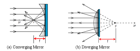
Figure 12: Converging and Diverging Mirrors
Figure 11: Three Rays Used in Locating Images with a Concave (Converging) Mirror
Ray 1. The magenta, parallel ray goes from the tip of the object, parallel to the principle axis, and then reflects back through the focal point.
Ray 2. The green, focal ray goes from the tip of the object, through the focal point, and then back parallel to the principle axis.
Ray 3. The orange, chief ray goes through the center of curvature, C, (at 2F) and then reflects back through C.
2
Using the diagram for a diverging mirror in Figure 13, complete the following sentences describing the matching results for a diverging mirror.
- Ray 1. The magenta, parallel ray goes from the tip of the object, parallel to the principle axis, and then reflects back .
- Ray 2. The green, focal ray goes from the tip of the object, toward the focal point, and then reflects .
- Ray 3. The orange, chief ray goes toward the center of curvature, C, (at 2F) and then reflects .
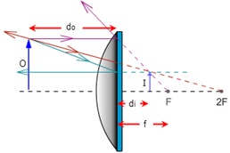
Figure 13: Three Rays Used in Locating Images with a Convex (Diverging) Mirror
3
Start with the object at the left end of the Ray Optics Tool and drag it slowly toward the mirror. Notice how the rays reflected from the mirror behave. Keep moving until the object is as close to the mirror as possible. Not a lot of variety!
4
Drag the object back to a point somewhere between 2F and F. (There's nothing special about this region. It just provides a good size figure.)
5
Take a Screenshot of the relevant section of the Ray Optics Tool. Save the image as "mirrors_diverging.png", and upload it.
6
In the figure provided in Sketch 6, create your own ray diagram. Be sure to include a pair of eyes at the end of your two rays.
Sketch 6: Diverging Mirror
7
How about the nature of the image for a diverging mirror? Check one for each category.
-
aReal or virtual? (real, virtual, no image)
-
bSize? (reduced, same size, enlarged)
-
cOrientation? (upright, inverted)
8
Take a Screenshot of the enlarged object and image displays at the top left of the screen, save it as "mirrors_diverging_cows.png", and upload it.
9
Describe the position or range of positions available to the image in this case.
Learning about the various image cases has a practical purpose. We need different image types for different situations. Sometimes we need an enlarged image and sometimes we need it reduced. But we also care about the orientation of the image. An upside down image in some cases could cause big problems. In other cases it would not be a problem.
10
Explore these considerations by matching up the image cases in Table 1 with the applications listed below. Each letter choice gets used exactly once.
-
aTelescope
-
bFlashlight, headlights, searchlights
-
cDentist's mirror
-
dShoplifting surveillance mirror
-
ePhotocopier in normal copy mode
-
fPhotocopier in enlarge mode
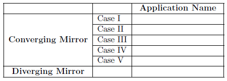
Table 1: Matching Image Cases to Typical Applications
IV. Equations and Sign Conventions for Spherical Mirrors
From our diagrams summarized in Figure 14, we can clearly see that the focal length and object distance geometrically determine the nature and location of any image. It should be very simple to produce equations to describe this geometry algebraically, and it is. There's one problem, however. For cases I–III, you get one pair of equations, then a slightly different pair for case V, and another slightly different pair for the diverging mirror. If we look at lenses while we're at it, we find a similar situation.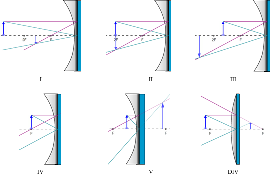
Figure 14: All Image Cases for Spherical Mirrors
A. Sign Conventions for Mirrors and Thin Lenses for Use with the Mirror or Thin Lens Equation and the Magnification Equation
The following two equations can be used to describe any of the five converging mirror or lens cases as well as diverging mirror or lenses. The equations will always take the same form but the signs of the values inserted into the equations are determined by the sign conventions. For example, if an image is formed 12 cm behind a converging mirror, you'll insert a value of –12 cm for di. And if you were solving for that particular image distance based on a given f and do, the resulting di will be found to have a negative value.Sign Conventions:
Focal Length, f (mirror or lens)
Focal Length, f (mirror or lens)
- + f: Converging Device
- – f: Diverging Device
- + do: Object is on the side of the device from which the light arrives. (Real Object)
- – do: Object is not on the side of the device from which the light arrives. (Virtual Object*)
- + di: Image on the side of the device where light travels after reflection or refraction. (Real Image)
- – di: Image not on the side of the device where light travels after reflection or refraction. (Virtual Image)
- + M, + hi: Image is upright relative to the object.
- – M, –hi: Image is inverted relative to the object.
Caution:
Be careful not to rephrase these conventions. They are easily broken. For example,
Be careful not to rephrase these conventions. They are easily broken. For example,
- "Image not on the side of the device where light travels" can't be translated into
- "Image on the side of the device where light comes from" because of differences in lenses and mirrors.
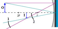
Figure 15: Virtual and Real Objects
Example of the Use of Equations and Sign Conventions:
If an object is placed 15.0 cm in front of a convex mirror and an image is formed 5.0 cm behind it, what must be the mirror's focal length? If the image is 2.5 cm tall, what is the magnification and what is the height of the object?
If an object is placed 15.0 cm in front of a convex mirror and an image is formed 5.0 cm behind it, what must be the mirror's focal length? If the image is 2.5 cm tall, what is the magnification and what is the height of the object?
-
do = +15.0 cm
The object is placed in front of the mirror where the light comes from. di = −5.0 cmThe image is behind the mirror, which is not where the light travels after reflection. hi = +2.5 cmWe know that an object in front of a diverging mirror produces upright images. f = ?, M = ?, ho = ?The signs of these unknowns will be determined as described in the following note.
A Note About Signs:
- When substituting the numeric values for these six variables into an equation, you must provide the signs for each variable. Do not insert an assumed sign for the unknown.
- When you solve for an unknown, the signs you provide for the knowns, along with the algebra, will produce the correct sign for the unknown being solved for.
| 1 |
| f |
| 1 |
| do |
| 1 |
| di |
f =
=
=
= −7.5 cm.
| di do |
| di + do |
| −5.0 cm × 15.0 cm |
| −5.0 cm + 15.0 cm |
| −75 cm2 |
| 10.0 cm |
M = −
=
Magnification Equation
describes the relative sizes of the object and image.
| di |
| do |
| hi |
| ho |
M = −
=
| di |
| do |
| hi |
| ho |
M = −
= −
= 0.33
| di |
| do |
| −5.0 cm |
| 15.0 cm |
ho = −hi ×
= −(2.5 cm) ×
= 7.5 cm
| do |
| di |
| 15.0 cm |
| −5.0 cm |
1
Let's practice. Insert a plus or minus sign, or N/A for each choice in Table 2. Assume that the object is in front of the mirror in each case. Only real objects are being considered. You might want to use the sign conventions chart and Figure 14. Notice how they say similar things in different ways. It's probably instructive to do this one column at a time.
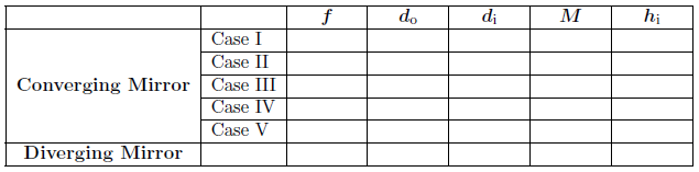
Table 2: Matching Variable Signs to Image Cases
The magnification can be tricky since its sign indicates one type of information while its value relative to 1.0 indicates another. This second consideration is due to the fact that it's a ratio of hi/ho, which can be >1, <1, or =1.
2
What does the sign of the magnification indicate about whether an image is upright or inverted?
-
aA positive sign indicates that the image is .
-
bA negative sign indicates that the image is .
3
The absolute value of the magnification can be less than 1.0, equal to 1.0 or greater than 1.0. Ex. 0.5, 1.0, or 3.2.
What does each of these indicate about the image?
-
aA magnification whose absolute value is less than 1.0 indicates that an image is .
-
bA magnification whose absolute value is equal to 1.0 indicates that an image is .
-
cA magnification whose absolute value is greater than 1.0 indicates that an image is .
4
A magnification of +3.2 means that the image is
times the size of the object and
.
5
A magnification of –0.32 means that the image is
times the size of the object and
.
B. Determining Magnification and Image Location with the Mirror and Magnification Equations
The example problem we've just explored should give you a good idea of the skills you need to work with image formation using mirrors. We'll finish this lab by doing similar explorations of each image case and both mirror types.1
Use the same mirror number selected for you in WebAssign for Part II.A.
2
Record the focal length you found for your mirror in Part II.A., step 12.
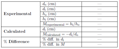
Table 3: Sample Data Table (Mirror type and case will be specified here.)
Procedure to complete table for each case:
Each data table has three sections—experimental, calculated, and % difference.
Each data table has three sections—experimental, calculated, and % difference.
a
Experimental data:
-
iSelect a representative object position for the case being examined and then measure and record do and di, using the centimeter ruler on the Ray Optics Tool.
-
iiTo measure ho and hi use the draggable grid on the Object and Image Close-up Screens as described below.
-
iiiAlso calculate and record hi/ho as your experimental value for the magnification. In the case of virtual images you won't have an experimental value for hi or M since you can't measure hi. In these cases you'll find "N/A" already inserted into the table.
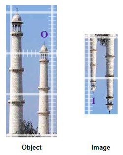
Figure 16: Object and Image Views of Taj Mahal
Procedure to complete table for each case (Continued):
To clarify the procedure, here's an example. For case I, which involves an object beyond the 2F point, you'll select and record an object distance and place the object at that point. You'll then adjust the Screen Position Tool to move the Optical Bench screen to be in focus and record its location as di. You'll then zoom in two times and use the magnified image grid to measure the height of the image. (We're assuming that the object height is 2.3 cm.) With these you'll calculate Mexperimental. You'll then calculate di, and Mcalculated using Equations 2
=
+
Mirror or Thin Lens Equation and 3
b
Calculated values:
-
iUse your measured do, and your assigned focal length in Equation 2to calculate the image distance, di.
=1 f
+1 do
Mirror or Thin Lens Equation1 di -
iiUse your measured do, your calculated di, and Equation 3M = −to compute your calculated M.
=di do
Magnification Equationhi ho
c
Percent differences:
-
iFinally find the percent differences between your experimental and calculated values for di, and M. This won't be possible in the case of virtual images. Again, you'll find N/A in the table for these cases.
| 1 |
| f |
| 1 |
| do |
| 1 |
| di |
M = −
=
Magnification Equation
. Finally, you'll compare these calculated values to the experimental values for the same quantities using percent difference. In some cases you won't be able to make some of these measurements or calculations because the virtual images can't be measured.
| di |
| do |
| hi |
| ho |
d
Show all the calculations for Mexperimental, di calculated, Mcalculated and the two percentage differences in the space beside the table. Remember that the percentage difference is computed as follows.
( 4 )
% difference =
| |experimental − calculated| |
| (|experimental + calculated|)/2 |
3
For the concave mirror—case I: do > 2f (R), do the following using the above procedure.
-
a–cComplete Table 3.
-
dShow your calculations of Mexperimental, di calculated, Mcalculated, and both percent differences.
4
For the concave mirror—case II: do = 2f (R), do the following using the above procedure.
-
a–cComplete Table 4.
-
dShow your calculations of Mexperimental, di ccalculated, Mcalculated, and both percent differences.
5
For the concave mirror—case III: f < do < 2f (R), do the following using the above procedure. (Be sure your object image does not go outside of the window.)
-
a–cComplete Table 5.
-
dShow your calculations of Mexperimental, di calculated, Mcalculated, and both percent differences.
6
For the concave mirror—case IV: do = f, do the following using the above procedure.
-
a–cComplete Table 6.
-
dNo calculations can be done for this case.
7
For the concave mirror—case V: do < f, do the following using the above procedure. (Be sure your object image does not go outside of the window.)
-
a–cComplete Table 7.
-
dShow your calculations of di calculated, Mcalculated, and the percent difference in di.
8
For the convex mirror, do the following using the above procedure.
-
a–cComplete Table 8.
-
dShow your calculations of di calculated, Mcalculated, and the percent difference in di.