Determination of e/m for the Electron
Introduction
In this experiment you will measure e/m, the ratio of the charge of an electron to the mass of an
electron. The currently accepted value for e/m is 1.758820 × 10¹¹ C/kg.
When an electron enters a region in which there is a uniform magnetic field, B, perpendicular to
the velocity, v, of the electron (Caution: The capital letter V will be used below to represent voltage.
Don't confuse v with V!), the electron experiences a force, F, with a magnitude given by the following equation.
The force is perpendicular to both v and B and its direction can be found by using the right-hand
rule. The force will cause the electron to move in a circular orbit with radius r (uniform circular
motion). Equating this force to the mass times the centripetal acceleration, we have the equation below.
Solving Eq. 2 for e/m, we get the following equation.
If the radius of the cyclotron orbit is measured, we can calculate e/m from Eq. 3. All we need is
the velocity of the electron. In our experiment, the electron is accelerated by a set of plates with a
potential difference, V, between them. The velocity of the electron can therefore be derived from
conservation of energy.
Solving Eq. 4 for the velocity, we get the following equation.
Finally, by substitution of the velocity from Eq. 5
into Eq. 3 and solving for e/m, we obtain Eq. 6
relating e/m to the potential difference, the magnetic field, and the radius of the electron's circular
orbit.
Apparatus
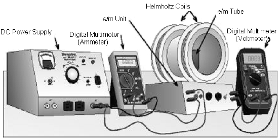
The set up of the equipment used in this experiment is shown in Fig. 1. The major items on the
e/m-unit are the three-element electron tube and the Helmholtz coils. The electron tube, Helmholtz
coils, and the power supplies for the tube filament and for the accelerating voltage are mounted in a
single base called the e/m unit. Controls and connectors on the front panel of this unit are (from left to
right):
-
•
Helmholtz Coil Connector: A pair of terminals to be connected to an external power supply
and ammeter so current can be supplied to the coils.
-
•
Power Switch and Indicator: Turns filament and accelerating-voltage supply on and off.
-
•
Focus Control: Adjust for best focus of electron beam.
-
•
Accelerating Voltage Control and Push Button: This control knob sets the accelerating
voltage to any value between 65 volts and 135 volts. The button allows the accelerating
voltage to be applied momentarily for observation of the electron beam.
-
•
Accelerating Voltage/100: A pair of terminals at which 1/100th of the accelerating voltage is
present—attach a 0-2 volt digital meter to read this 1/100th of the accelerating voltage.
The current to the Helmholtz coils is supplied by an external DC power supply. A multimeter is
used to measure the current to the Helmholtz coils. The electron tube and the Helmholtz coils are
described in detail below.
The Electron Tube
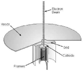
An "electron gun" is mounted within the electron tube with its centerline coincident with the
vertical axis of the tube. The electron gun has three elements:
-
a
an indirectly heated cathode that supplies the electrons.
-
b
a grid, charged to a positive potential with respect to the cathode, which serves to focus the
electron beam.
-
c
a circular disk, which is held at a high positive potential with respect to the cathode, which
serves to accelerate the electrons.
The electron beam is projected vertically through a small hole in the center of the disk. The disk is
mounted horizontally on the upper end of the electron gun. Four circles, with centers coincident with the hole and of radii 0.50, 1.0, 1.5, and 2.0 cm, are marked on the upper face of the disk. The bulb and
disk are coated with a material that fluoresces when struck by electrons. The tube contains a trace of
an inert gas that aids in focusing the electron beam as well as causing the beam to make a visible
trace.
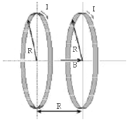
The Helmholtz Coil
The magnetic field is provided by a pair of identical circular coils arranged so that the distance
between the coils is equal to the radius of the coils. Such an arrangement, called the Helmholtz Coils,
provides a highly uniform magnetic field in the region at and near the center of the coil pair.
The magnetic field produced by the Helmholtz coils is proportional to the electric current, I, in the
coils.
At the exact center of the Helmholtz coils, the value of j is given theoretically by:
( 8 )
j =
μ0 | 3 |
| |
where:
-
μ0 = constant = 1.256 × 10⁻⁶ Tesla · meter/Ampere.
-
N = number of turns of wire on a coil (marked on the coils).
-
R = radius of coils.
The values of N and R for the Helmholtz coils used in this lab are: N = 196 turns, and R = 0.105 meters. Substitution of these values into Eq. 8j =
μ0 | 3 |
| |
gives: j = 1.678 × 10⁻³ T/A, or 1.678 mT/A. Eq. 7B = jI
,
with the above calculated value of j, will be used to determine the magnetic field from measured
values of the current.
Procedure
Connect the apparatus according to the arrangement shown in Fig. 1 and start taking data
following the steps outlined below:
1
To measure coil current,
use the 10A scale on the multimeter (using the 300 mA connection
will blow a fuse!). To turn on the power to the Helmholtz coils, set the voltage control on the
external DC power supply to its minimum setting. Turn the supply ON and carefully and slowly
advance the voltage control while observing the ammeter. If the meter gives a positive reading, all is
well; if not, you have wired the meter backwards. Turn the supply OFF and reverse the ammeter
connections.
Do not allow the Helmholtz coil current to exceed 5A!
2
Turn the power switch on the
e/
m unit ON and
wait 2 minutes for the tube filament to warm
up. Observations of the electron beam in the vacuum tube must be carried out with the room lights
off. Note there is a push button that allows the accelerating voltage to be applied to the tube
momentarily; this feature is necessary because the tube has a rather short lifetime.
Replacement
tubes are expensive, so apply accelerating voltage only long enough for your observations.
3
The tube filament, on the other hand, is best left turned ON; leave the power switch ON for as
long as needed to perform your measurements, and turn it OFF only when you are finished.
4
When the tube has reached operating temperature, set the accelerating voltage to a relatively
low value (around 50 volts). Note: the terminals that provide the scaled accelerating voltage
(
Vacc/100) are active only when the push button is depressed.
Again, do not allow the Helmholtz
coil current to exceed 5A!
5
With accelerating voltage applied to the tube (button depressed), increase the Helmholtz coil
current until the electron beam bends over and lands on the outermost target ring; adjust the FOCUS
control to obtain as fine a beam as possible, and then make adjustments to the Helmholtz coil current
to put the electron beam exactly on the target ring. Inability to judge when the electron beam is
exactly on the ring is one source of uncertainty. Since the focusing effect of the grid and the inert gas
causes some of the electrons to lose kinetic energy, it is best to use the outermost edge of the beam as
it strikes the ring. Taking several measurements of the current may reduce errors. Record the
accelerating voltage, Helmholtz coil current (take measurements up and down scale), and the
diameter,
d, of the electron beam path on your data sheet.
6
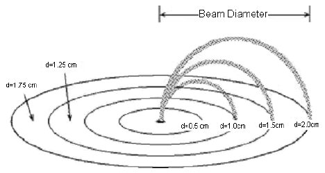
Repeat step 5, keeping
the accelerating voltage fixed,
but increasing the Helmholtz
coils current until the beam path
has a diameter of 1.75, 1.5,
1.25, and 1.0 cm as shown in
Figure 4. Measure and record
the current corresponding to
each of the diameters. For the
1.75 and 1.25 cm diameters, the
electron beam must strike at the
mid-point between two target
rings.
It may not be possible for the beam to reach the 2.0 cm diameter line.
7
Change the accelerating voltage (which is actually 100 times higher than the scale values) to a
somewhat higher value (around 80 - 90 volts) and repeat steps 5 and 6.
After collecting your data, try using a bar magnet to "steer" the beam of charged particles. What
happens when you bring the north end of the magnet towards the beam? What happens when you
reverse the orientation of the magnet? Confirm your understanding of the direction of the
Lorentz force and the right-hand rule by using a compass to determine the direction of the magnetic
field produced by the Helmholtz coils. (Remember that N is short for the north-seeking pole of a
magnet, which means that the Earth's geographic north pole acts like a magnetic south pole.) Draw a
sketch of the Helmholtz coils and the deflected beam to show the direction of the current in the coils
and the resulting magnetic field.
8
Turn off the power supplies and multimeters. Disconnect all wires and return them to the
storage bin.
Be sure that you and your TA each initial your data sheets, and that you hand in a copy of your
data before you leave the lab.
Analysis
An important modification must be made to Eq. 6
before it can be used to calculate e/m. The
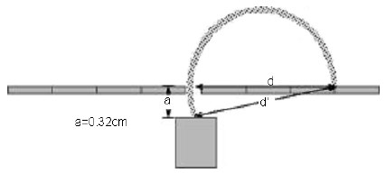
modification is needed because the cathode where the electron beam originates is situated a distance
a = 3.2 ± 0.5 mm below the exit hole.
As the figure above shows, the diameter, d, that is measured is not the actual diameter, d', for the
electron's orbit. The actual diameter can be derived by using the Pythagorean equation shown below.
( 9 )
d' =
 | d2 + a2 |
Substitution of r = d'/2 and Eq. 9d' =
| d2 + a2 |
into Eq. 6
, we get the following equation.
Note: the use of the letter 'V' in this equation is to indicate a variable for voltage. This does NOT
mean that you calculate B using 8 volts, but by using 8 times the voltage measured!
1
Using a spreadsheet, calculate a table of
d, 1/(
d2 +
a2), average
I,
uI,
B,
uB,
B2, and
uB2 from the data for the lower accelerating voltage (≈50V).
2
Plot
B2 vs. 1/(
d2 +
a2) and do a linear least square fit. Determine the slope and the intercept of
the fitted curve.
3
From the slope, determine the value for
e/
m in C/kg using
Eq. 10
. Be sure to use the
appropriate units for the variables
B and
d. The uncertainty in
e/
m can be calculated from the
uncertainty in
V and the uncertainty in the slope.
4
Repeat steps 1, 2, and 3 for the data obtained from the higher accelerating voltage.
5
Take the weighted average of the two values of
e/
m obtained by using the formula:
e/m = w1(e/m)1 + w2(e/m)2.
The weights
w1 and
w2 are taken to be proportional to the inverse of the
square of the uncertainty of each
e/
m respectively. In this way the value of
e/
m with the smaller
uncertainty will be given more weight. Thus,
where the proportionality constant,
k, is chosen to normalized the weights so that
w1 +
w2 = 1. The
value of
k is given by the equation below.
Calculate the values of
w1 and
w2 and check if
w1 +
w2 = 1. Calculate the weighted average of
e/
m.
6
Calculate the uncertainty of the weighted average value of
e/
m using the formula:
u =
 | k |
.
Discussion
Compare your experimental value of e/m to the accepted value. Discuss quantitatively the
possible sources of error.
Remember to pledge your work.