- Contents >
- Object and Image Distances for Thin Lens

Object and Image Distances for Thin Lens
Topics and Files
Optics Topics
-
Thin lens formula
-
Concave mirror
Equipment List
Introduction
This lab has two parts.
The purpose of Experiment 1 is to determine the relationship between object distance and image distance for a thin convex lens. Use a light source, optics bench, lens, and viewing screen to measure object distance, image distance, and image size.
The purpose of Experiment 2 is to measure the focal length of a concave mirror. Use a light source, concave mirror, and half screen accessory on an optics bench to measure the focal length of the concave mirror.
Background
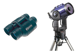
All of the technological pieces of equipment you see pictured here make use of lenses.
You can find the use of lenses in surgery. Surgeons use lenses to get a closer look and make surgical procedures safer. The development of miniature cameras and lenses have made many surgical procedures less invasive.
A lens even makes it possible for the laser beam in your CD player to read the disk and play your favorite music.
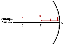
Concave and convex mirrors are examples of spherical mirrors. Spherical mirrors can be thought of as a portion of a sphere which was sliced away and then silvered on one of the sides to form a reflecting surface. Concave mirrors are silvered on the inside of the sphere and convex mirrors are silvered on the outside of the sphere. If a concave mirror is thought of as being a slice of a sphere, then there would be a line passing through the
center of the sphere and attaching to the mirror in the
exact center of the mirror. This line is known as the
principal axis. The point in the center of sphere from
which the mirror was sliced is known as the center of
curvature and is denoted by the letter C in the diagram.
The point on the mirror's surface where the principal
axis meets the mirror is known as the vertex and is
denoted by the letter A in the diagram. The vertex is
the geometric center of the mirror. Midway between
the vertex and the center of curvature is a point known as the focal point; the focal point is denoted by the letter F in the diagram. The distance from the vertex to the center of curvature is known as the radius of curvature (abbreviated by R). The radius of curvature is the radius of the sphere from which the mirror was cut. Finally, the distance from the mirror to the focal point is known as the focal length (abbreviated by f).
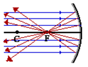
The focal point is the point in space at which light incident towards the mirror and traveling parallel to the principal axis will meet after reflection. The diagram below depicts this principle. In fact, if some light from the Sun was collected by a concave mirror, then it would converge at the focal point. Because the Sun is such a large distance from the Earth, any light rays from the Sun which strike the mirror will essentially be traveling parallel to the principal axis. As such, this light should reflect through the focal point.


