Lab 6 - Optics
Introduction
Geometric optics is one of the oldest branches of physics, dealing with the laws of reflection and refraction. Reflection takes place on the surface of an object, and refraction occurs when light passes through an object. The Law of Reflection was known to the ancient Greeks who made measurements that supported this law. The Law of Refraction, however, was not formulated mathematically until almost 1500 years later. Image formation by lenses and mirrors is explained by these two laws. Lenses and mirrors are the basic components of many common optical devices such as cameras, telescopes, eyeglasses, binoculars, and microscopes. In geometric optics light is represented as rays coming from a light source. When these rays encounter a mirror, lens, or prism, for example, they bend or change direction. In this experiment you will examine various lenses and mirrors and the focusing effect they have on light rays.Discussion of Principles
Reflection by a Plane Mirror
When light is incident on a surface, some of the light is reflected back while some of it is transmitted or absorbed. A plane mirror is a highly polished surface with minimal absorption or refraction of light. Nearly all of the light is reflected back. There are an infinite number of rays coming from a single light source. However, when analyzing the behavior of light using the ray model, we use just one, two, or three rays to show the path of the rays and image formation. These are known as ray diagrams. To understand reflection using the ray model, we need to first define certain terms. The incident ray is a ray from the light source incident on the plane mirror. The angle of incidenceθi
is the angle between the incident ray and the normal (perpendicular) at the point of incidence. The reflected ray is the path of the ray after reflection by the surface. The angle of reflection θr
is the angle between the reflected ray and the normal at the point of incidence (see Fig. 1). Arrows indicate the path of light rays.
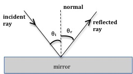
Figure 1: Reflection in a plane mirror
( 1 )
θi = θr
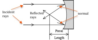
Figure 2: Reflection from a concave mirror
Refraction at a Plane Surface
When light is incident on the boundary between two optical media such as air and glass, some of it is reflected at the boundary, and some of it passes through and is refracted (bent), as shown in Fig. 3.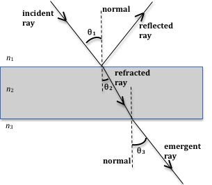
Figure 3: Reflection and refraction of light at air-glass and glass-air boundaries
(n1 < n2),
it will bend toward the normal. The angle of refraction θ2
in the second medium will be less than the angle of incidence θ1
in the first medium. On the other hand, when light goes from a denser medium into a rarer medium (n1 > n2),
it will bend away the normal.
In Fig. 3, light is traveling from air into glass and then emerges back into air. Here n1 < n2
and therefore the refracted ray bends toward the normal. This refracted ray now goes from glass (denser medium) into air (rarer medium) and therefore it bends away from the normal. The angle θ2
between the refracted ray and the normal line is referred to as the angle of refraction.
The Law of Refraction is given by Snell's Law, which stated mathematically is
( 2 )
n1 sin θ1 = n2 sin θ2
( 3 )
n2 sin θ2 = n3 sin θ3.
n3
equals n1
as in Fig. 3, then θ3
will equal θ1
and Eq. (3)n2 sin θ2 = n3 sin θ3.
is essentially the same as Eq. (2)n1 sin θ1 = n2 sin θ2
. Also note that the emergent ray is parallel to the incident ray but shifted laterally to the right.
Refraction at Curved Surfaces
Lenses are optical devices that refract light and in so doing they alter the path of light rays. There are two basic types of lenses: converging and diverging. Fig. 4(a) shows a converging (convex) lens. Parallel light rays incident on the lens get refracted and converge to a point on the other side of the lens. This point of convergence is known as the focal point (or focus) of the lens. The distance from the centerline of the lens to the focal point is known as the focal length of the lens. It depends on the radius of curvature of both lens surfaces and on the index of refraction of the lens material. The focal length of a converging lens is positive.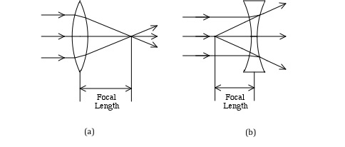
Figure 4: Converging and diverging lenses
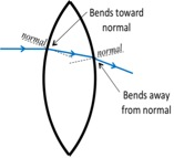
Figure 5: Path of light ray through a lens
Objective
The objective of this experiment is to study the path of light rays due to reflection and refraction at plane and curved surfaces and to verify the Law of Reflection in a plane mirror and Snell's Law of Refraction.Equipment
- Acrylic block
- Light ray box
- Plane mirror
- Converging and diverging lenses
- Converging mirror
- Sheets of paper
- Ruler
- Protractor
Procedure
Please print the worksheet for this lab. You will need this sheet to record your data. You will use a light ray box to produce parallel rays of light into which you will insert various optical components to observe their effect on the rays. You will trace the rays on sheets of white paper, which will constitute part of your data for this experiment.Procedure A: Reflection from a Plane Mirror
1
Use the light box with one light ray, and place a sheet of white paper on the table in front of the light box.
Place the plane mirror in the path of the light ray and orient it so that the ray is at some angle other than 90° to the surface of the mirror.
2
Trace the front surface of the mirror, the incident ray, and the reflected ray.
To trace the rays, mark two points for each ray and then draw straight lines with the ruler later when the mirror is out of the way.
3
Remove the mirror and draw the normal line where the ray contacts the mirror surface.
4
Label the incident ray, the reflected ray, the normal line, θi,
and θr.
5
Measure and record the angle of incidence and the angle of reflection on the worksheet.
6
Calculate the percent difference between the angle of incidence and the angle of reflection and record it on the worksheet. See Appendix B.
Checkpoint 1:
Ask your TA to check your sketch and values.
Ask your TA to check your sketch and values.
Procedure B: Focal Length of a Concave (Converging) Mirror
Note: Use angles other than zero for the angle of incidence.7
Use the light box with three light rays, and place a new sheet of white paper on the table in front of the light box.
Adjust the light rays so that they are parallel by sliding the front of the light box in or out.
One way to ensure that the rays are parallel is to shine the three rays onto a distant wall and adjust the box so that the rays are as close together on the wall as they are coming out of the box.
Place a concave mirror in the path of the light rays and orient it so that the mirror is perpendicular to the rays, i.e. when the center ray is incident on the middle of the mirror, it is reflected back on itself.
8
Trace the front surface of the mirror, the incident rays, and the reflected rays.
To trace the rays, mark two points for each ray and then draw straight lines with the ruler later when the mirror is out of the way.
9
Remove the mirror and draw the normal lines where each ray is incident on the mirror surface.
Remember that normal lines must be perpendicular to the surface of the mirror. Also think about how the angle of incidence and the angle of reflection are related to each other.
10
Label the incident rays, the reflected rays, the normal lines, θi,
and θr.
11
Measure the angle of incidence and the angle of reflection for each ray and record the values in Data Table 1 on the worksheet.
12
Calculate the percent difference between the angle of incidence and the angle of reflection for each ray and record it in Data Table 1 on the worksheet.
Checkpoint 2:
Ask your TA to check your sketch and values.
Ask your TA to check your sketch and values.
Procedure C: Refraction in an Acrylic Block
18
Insert the slotted plastic piece into the front of the light box so that only one light ray comes out.
Place a white sheet of paper flat on the table in front of the light box so that the light ray can be seen on the paper.
Lay the rectangular acrylic block flat on the paper and rotate it so that the light ray is incident at some angle other than 0° as shown in Fig. 6.
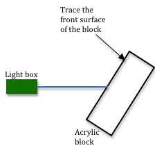
Figure 6: Set-up for Procedure D
19
On the white paper, trace the front edge of the acrylic block and draw the light ray from the light box to the acrylic block with a ruler.
To trace the light ray, mark a point near the light box and the point where the light ray enters the block, so that you can draw a straight line later by joining these two points.
Also mark the spot where the refracted ray emerges on the opposite side of the block.
Do not trace the faint rays that are reflected from the surface of the acrylic block.
20
Remove the acrylic block and use a ruler to draw the path of the light ray inside the block by connecting the point where the ray entered the block to the point where the ray exited the block.
21
Draw the normal line at the point where the light ray enters the acrylic block.
Remember, the normal is perpendicular to the surface, and it must be drawn at the point where the ray is incident on the surface.
22
Label the boundary between air and acrylic, the incident ray, the refracted ray, the normal at both surfaces, θi,
and θr.
Your diagram should now look like Fig. 7, with the exception that the angles of incidence and refraction are not shown to ensure that you can identify them on your own.
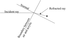
Figure 7: Tracing of light rays
23
Measure the angles of incidence and refraction and record them on the worksheet.
24
Use Snell's Law and the angles measured in step 23 to calculate the index of refraction, n, of the acrylic block. Record this value on the worksheet.
Use n = 1.0 for the index of refraction of air.
Checkpoint 3:
Ask your TA to check your sketch and values.
Ask your TA to check your sketch and values.
Procedure D: Focal Length of a Converging Lens
25
Set the light box to produce three rays.
Adjust the light rays so that they are parallel by sliding the front of the light box in or out.
One way to ensure that the rays are parallel is to shine the three rays onto a distant wall and adjust the box so that the rays are as close together on the wall as they are coming out of the box.
26
Place a new sheet of white paper on the table in front of the light box.
Place the converging lens in the path of the light rays so that the lens is perpendicular to the rays and one ray passes straight through the middle of the lens as shown in Fig. 4(a).
The lenses used in the lab only have one curved side, so orient the lens such that the flat side is closer to the light box.
27
Trace the front and back surfaces of the lens.
Using a ruler, trace the three incident rays and the three refracted rays until they intersect.
To trace the rays, mark two points for each ray and then draw straight lines with the ruler later when the lens is out of the way.
Do not trace the faint rays that are reflected from the surface of the lens.
28
Remove the lens and label the incident rays, the refracted rays and the focal point.
29
Measure the focal length, which is the distance along the middle ray from the flat side of the lens to the focal point.
On your sheet of paper, clearly identify the two points to which this distance refers.
Checkpoint 4:
Ask your TA to check your sketch and values.
Ask your TA to check your sketch and values.
Procedure E: Focal Length of a Diverging Lens
30
Use the light box with three light rays, and place a new sheet of paper on the table in front of the light box.
Place the diverging lens in the path of the light rays so that the lens is perpendicular to the rays and so that one ray passes straight through the middle of the lens as shown in Fig. 4(b).
Orient the lens such that the flat side is closer to the light box.
31
Trace the front and back surfaces of the lens.
Trace the three incident rays and the three refracted rays.
To trace the rays, mark two points for each ray and then draw straight lines with the ruler later when the lens is out of the way.
Do not trace the faint rays that are reflected from the surface of the lens.
32
Remove the lens and extend the refracted rays back through the lens, as shown in Fig. 4(b), to find the focal point.
33
Label the incident rays, the refracted rays, and the focal point.
34
Measure the focal length, which is the distance along the middle ray from the flat side of the lens to the focal point.
Remember that the focal length for a diverging lens is negative.
On your sheet of paper, clearly identify the two points to which this distance refers.
Checkpoint 5:
Ask your TA to check your sketch and values.
Ask your TA to check your sketch and values.

