Module 7 – Ohm's Law
Introduction
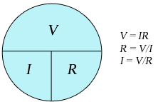
In this experiment, you will study Ohm's Law, the most fundamental relation used in the analysis of electrical circuits. Ohm's Law relates the quantities of voltage, electric current, and resistance in one easy-to-use equation. This illustration provides you with an aid to help you remember the three forms of Ohm's Law. If you know two of the three quantities, it is possible to determine the third.
Figure 1
Simple Electric Circuit
The simplest electric circuit contains a source of electric power and a resistance. The power supply is a source of electrical energy, which is used to supply electric current that flows through the resistance in the circuit. A water pump analogy is often used to help illustrate the concept. The water pump creates a difference in pressure between the two ends of the pipe. This pressure difference causes the water to flow through the pipes as it moves from high pressure to low pressure. As the pressure is increased, the flow of water also increases.
Figure 2: Water pump and electric circuit analogy
Electric Current
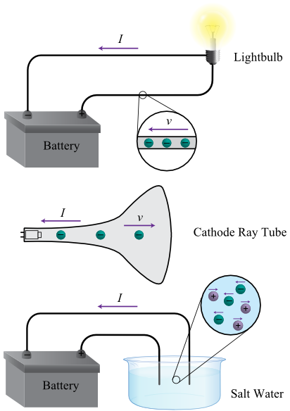
Electric current is defined as the amount of charge that flows each second. As you can see in the illustration, an electric current can exist in wires, solutions, and even in the vacuum of a television tube. The unit of electric charge is the coulomb, so electric current has the unit coulomb per second (C/s); this is also called the ampere (A). Meters used to measure electric current are placed in line with the circuit components so that the same current flowing through the circuit also flows through the meter.
Figure 3
Voltage
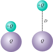
As you have seen, the voltage in an electric circuit is analogous to the pressure created by a water pump. More precisely, however, the voltage in an electric circuit is a measure of the amount of electrical potential energy per charge between two points in the circuit. Take a look at the illustration. Suppose you have an accumulation of electric charge (a battery or power supply). This electric charge will create an electric field that exerts an electric force on the charge located in the field. In our case, assume that the large positive charge is fixed, and that the small negative charge is able to move. The work required to move the negative charge will be the force required to overcome the electric attraction times the distance moved.
Figure 4
Resistance
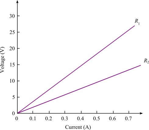
Resistance is the opposition to current flow. In the water pump analogy, the more narrow the pipe, the less water will flow. Similarly, the greater the electrical resistance for a given voltage, the less electric current will exist. Consider the flow of electric charge through a conducting wire. As the charge begins to move, it collides with the atoms in the wire. This impedes the current flow. The more collisions, the greater the resistance to current flow. If each charge has greater potential energy, it will tend to move through the wire with greater kinetic energy as it "falls" from point to point, and the electric current will increase. In other words, the voltage and current are directly proportional. The amount of increased current for an increase of voltage depends on the resistance in the circuit. Ohm's Law summarizes these facts in a simple, easy-to-use equation.
Voltage is proportional to Current.
Voltage = Current × Resistance
The unit of electrical resistance is the ohm (Ω); it is equal to 1 volt/ampere.
The illustration demonstrates this proportionality between voltage and current. Notice that the slope of
the line is equal to the value of the resistance in the circuit.
Voltage = Current × Resistance

Figure 5
Procedure
You will observe the experiment performed and fill in your data sheets.1
Open the experiment instructions and worksheet.
-
•Ohm's Law Experiment Instructions (HTML or PDF)
-
•Ohm's Law Experiment Worksheet
2
After you have opened the instructions and worksheet, select and watch the Experiment Video (the Experiment Video is available in your course LMS).
3
Record your data in the worksheet. (You will need it for the lab report assignment in WebAssign.)
