WebAssign is not supported for this browser version. Some features or content might not work. System requirements

WebAssign

Welcome, demo@demo

(sign out)

Saturday, March 29, 2025 03:02 EDT

Home My Assignments Grades Communication Calendar My eBooks

Striebig - Discovering Engineering Design - 1/e (Homework)

James Finch

Engineering, section 1, Fall 2019

Instructor: Dr. Friendly

Current Score : 1 / 23

Due : Sunday, January 27, 2030 12:00 EST

Last Saved : n/a Saving...  ()

Question
Points
1 2 3 4 5 6 7 8 9 10
1/1 –/1 0/2 –/21 –/11 –/5 –/3 –/1 –/4 –/7
Total
1/23 (4.3%)
  • Instructions

    Striebig's DISCOVERING ENGINEERING DESIGN IN THE 21ST CENTURY: AN ACTIVITIES-BASED APPROACH, with WebAssign digital resources, offers beginning engineering students experiential engineering practice that helps contextualize engineering analysis and design. Active learning exercises describe and model fundamental engineering theories throughout to reveal how these theories impact engineering design processes. Applicable engineering fields of study are also identified and explored through hands-on learning examples that offer students practical experience.

    This demo assignment allows many submissions and allows you to try another version of the same question for practice wherever the problem has randomized values.

    WebAssign provides a wide range of exercises that enable you to:
    • Let students self-remediate with question-level help (#1-10: Read It)
    The answer key and solutions will display after the first submission for demonstration purposes. Instructors can configure these to display after the due date or after a specified number of submissions.

Assignment Submission

For this assignment, you submit answers by question parts. The number of submissions remaining for each question part only changes if you submit or change the answer.

Assignment Scoring

Your last submission is used for your score.

1. 1/1 points  |  Previous Answers StriebigEngDesign1 1.1.004. My Notes
Question Part
Points
Submissions Used
1
1/1
1/100
Total
1/1
 
  • This exercise will Let students self-remediate with question-level help.
  • Read It links are available as a learning tool under each question so students can quickly jump to the corresponding section of the eTextbook.

The National Society of Professional Engineers (NSPE) has established a Code of Ethics for engineers. Look up and write down the six fundamental canons of the NSPE Code of Ethics. (Your submission will be graded by your instructor after the due date based on its accuracy. Your grade may change.)

Score: 1 out of 1

Comment:

Your work in question(s) will also be submitted or saved.
Viewing Saved Work Revert to Last Response
2. /1 points StriebigEngDesign1 1.3.006. My Notes
Question Part
Points
Submissions Used
1
/1
0/100
Total
/1
 
  • This exercise will Let students self-remediate with question-level help.
  • Read It links are available as a learning tool under each question so students can quickly jump to the corresponding section of the eTextbook.

Force is a derived quantity determined from the acceleration of an object multiplied by the mass of an object. Derive the dimensions used to create units for a force acting on an object from the fundamental quantities of length, mass, and time. Also, show the SI units of force in your derivation. (Your submission will be graded by your instructor after the due date based on its accuracy. Your grade may change.)

This answer has not been graded yet.

Need Help? Watch It

Your work in question(s) will also be submitted or saved.
Viewing Saved Work Revert to Last Response
3. 0/2 points  |  Previous Answers StriebigEngDesign1 1.3.007. My Notes
Question Part
Points
Submissions Used
1 2
0/1 0/1
1/100 1/100
Total
0/2
 
  • This exercise will Let students self-remediate with question-level help.
  • Read It links are available as a learning tool under each question so students can quickly jump to the corresponding section of the eTextbook.

The highest mountain in the world is Mount Everest in Nepal and China. The peak of Mount Everest is 29,032 feet above sea level. How many miles high is this?
Incorrect: Your answer is incorrect.
Your response differs from the correct answer by more than 100%. mi
What is the elevation in meters?
Incorrect: Your answer is incorrect.
Your response differs significantly from the correct answer. Rework your solution from the beginning and check each step carefully. m

Need Help? Watch It

Your work in question(s) will also be submitted or saved.
Viewing Saved Work Revert to Last Response
4. /21 points StriebigEngDesign1 1.5.011-018. My Notes
Question Part
Points
Submissions Used
1 2 3 4 5 6 7 8 9 10 11 12 13 14 15 16 17 18 19 20 21
/1 /1 /1 /1 /1 /1 /1 /1 /1 /1 /1 /1 /1 /1 /1 /1 /1 /1 /1 /1 /1
0/100 0/100 0/100 0/100 0/100 0/100 0/100 0/100 0/100 0/100 0/100 0/100 0/100 0/100 0/100 0/100 0/100 0/100 0/100 0/100 0/100
Total
/21
 

Can a Big Bug Create a Lethal Force?

Have you ever heard the expression Sometimes you're the windshield, sometimes you are the bug? How much damage can a little bug cause? If you are riding a bicycle or motorcycle at a high velocity and hit a flying bug, can you feel that? How hard did you hit that bug, which, in engineering terms, means, how much force was imparted onto you when you hit the bug? And what if that bug was a big bug? What if it hit you under the neck in a vulnerable area of your throat? Could that cause serious life-threatening harm?
You decide to calculate how much force is imparted onto you when you hit the bug.
In some of the steps below, you will be asked to submit a file. Submit a file with a maximum size of 15 MB. Your submission will be graded by your instructor after the due date based on its accuracy. Your grade may change.
  • To get started, determine the bug weight in kilograms and enter the data from the following table into a spreadsheet program like Excel or Google Sheets.
    Bug Weight [g] Bug Weight [kg]
    0.143
    11.4
    57.5
  • Using the calculations from Step 1, calculate the magnitude of the force in newtons for each bug and enter the data into the following table.
    Bug Weight [g] Deceleration [m/s2] Force [N]
    0.143 530,000
    11.4 15,000
    57.5 7,100
    Combine the data from the table in Step 1 and the above table, enter the data into a spreadsheet program like Excel or Google Sheets and plot the data.

    This answer has not been graded yet.

  • Graph the data points in the previously combined tables in an Excel graph with acceleration (y-axis) versus mass (x-axis). Plot the data on a scatterplot and insert a power function trend line. Note the equation and
    R2
    value of the trend line on the graph.

    This answer has not been graded yet.

  • Use your Excel spreadsheet to determine a power function trend line. (Use the mass in kg. Enter A in m/s2.)
    y = AxB
    A
    = m/s2
    B
    =
    Use the trend line equation to calculate the mass (in kg) of a bug needed to impact exactly the lethal force required by a blow to the larynx (338 N). (Use the values entered in the previous equation.)
    kg
  • Use the table in your Excel spreadsheet, the graph and the power function trend line that you have built in the previous steps.
    Determine the force from the impact of a bug in units of newtons for a motorcycle traveling at 40 m/s and a 57.5 g bug using the previous data to interpolate the required values. Write the relevant equations. Label your variables. Show your algebraic work and any unit conversions required.

    This answer has not been graded yet.

    Calculate the magnitude of the force in newtons associated with each different velocity and complete the following table using a spreadsheet.
    Motorcycle Velocity [m/s] Bug Weight [kg] Deceleration [m/s2] Force [N]
    40 0.0575 7,100
    54 0.0575 22,000
    90 0.0575 41,000
  • Graph the data points from the table in Step 5 in an Excel graph with acceleration (y-axis) versus velocity (x-axis). Plot the data on a scatterplot and insert a logarithmic function trend line. Note the equation and
    R2
    value of the trend line on the graph.

    This answer has not been graded yet.

  • Which of the following regression models most accurately correlates deceleration with velocity for the data in the table in Step 5?
        
    Calculate the magnitude of the force (in N) imparted when a 65 g bug impacts an object if the speed differential between the bug and the object is 45 m/s. (Use the regression model you chose.)
    N
  • Using the data from the combined tables that you built in Steps 5 and 6, graph the data points in an Excel graph with acceleration (y-axis) versus velocity (x-axis).
    Plot the data on a scatterplot and insert a logarithmic function trend line. Determine the equation that relates the force imparted to a motorcycle driver at various velocities from a curve fit of the graphical data. (Enter A and B in m/s2.)
    y = A + B ln(x)
    A
    = m/s2
    B
    = m/s2
    Use this relationship to determine the speed (in m/s) that a motorcycle would have to be traveling in order to impart a lethal force (338 N) to a motorcyclist from a 10 g cicada. (Use the values entered for the previous equation.)
    m/s
Your work in question(s) will also be submitted or saved.
Viewing Saved Work Revert to Last Response
5. /11 points StriebigEngDesign1 1.6.026-033. My Notes
Question Part
Points
Submissions Used
1 2 3 4 5 6 7 8 9 10 11
/1 /1 /1 /1 /1 /1 /1 /1 /1 /1 /1
0/100 0/100 0/100 0/100 0/100 0/100 0/100 0/100 0/100 0/100 0/100
Total
/11
 

Designing a Simple Machine

Prior to the use of modern currency, payments were made by trading goods. Those goods could sometimes be paid for with precious metals: copper, silver, or gold. The copper, silver, and gold coins were literally "worth their weight," so a method had to be devised to determine the weight of the metal offered in copper, silver, and gold compared to the good being purchased. Merchants maintained scales or balances for this purpose.
A balance is a simple mechanical device that illustrates many fundamental principles and can be easily built and assembled. By designing a balance according to the following steps, you will be doing the following:
  • Utilizing the density and specific gravity of solid and liquid materials to perform a force balance
  • Utilizing the principles of geometry and algebra to calculate the weight and force acting on the balance beam
  • Reading engineering drawings to relate numerical values to real parts and components of the balance.
Two drawings show a PVC pipe and endcap that will be used to hold water in the balance. A third drawing shows a wooden balance beam.
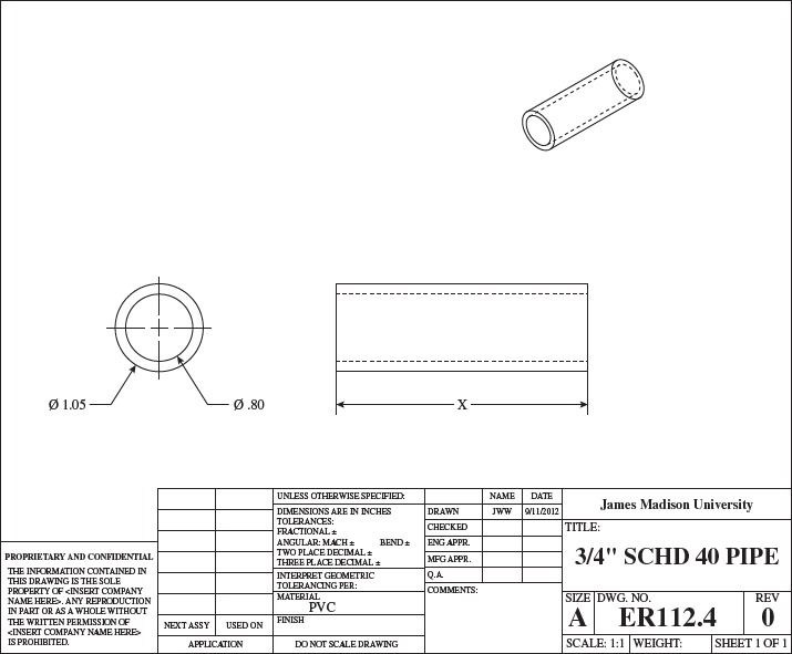
A diagram of a 34 SCHD 40 pipe is shown. The pipe is represented as a hollow cylinder of length x, outer diameter 1.05 inches, and inner diameter 0.80 inches. Both ends of the pipe are open. Drawn by JWW during date 9/11/2012 for James Madison University. Scale is 1:1 with Size A.
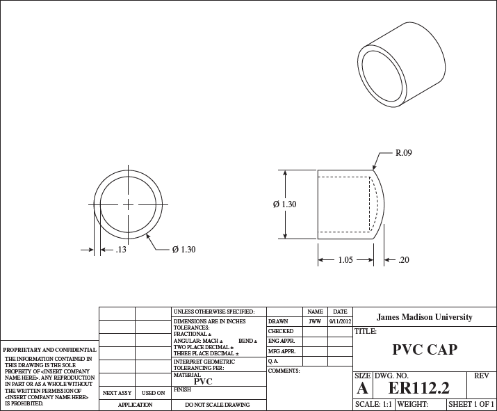
A diagram of a PVC cap is shown. The cap is represented as a hollow cylinder of length 1.05 inches, outer diameter 1.30 inches, and thickness 0.13 inches, with the left end of the cap open and the right end of the cap closed. The closed end is represented as a dome with its peak along the axis of the cylinder, base flush against the cylinder, with width of base equal to the outer diameter of cylinder, and height of 0.20 inches from base to peak. The cap is labeled R.09. Drawn by JWW during date 9/11/2012 for James Madison University. Scale is 1:1 with Size A.
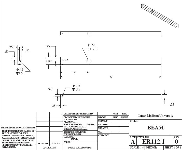
An engineering drawing shows five views of a wooden beam with several holes drilled into it. All dimensions are in inches.
  • The first view of the beam, at the left of the diagram, is a vertical rectangle showing the cross section of the beam. The cross section has a height of 1.50 and a width of 0.75. The distance from the beam's center to the right side is approximately 0.38.
    • The first hole is drilled from left to right completely through the cross section.
    • The second hole is drilled into the page, has a diameter of 0.19, and is drilled to a depth of 1.50.
    Both the top of the first hole and the center of the second hole are a distance of 0.50 from the top side of the cross section.
  • The second view is a view of the beam from the top. Hidden lines show the first hole drilled completely through the beam from one long face upward to the other, perpendicular to the normal to the cross section. The second hole is drilled from the left side a short distance to the right, coaxial with the normal to the cross section.
  • The third view is a side view of the beam. The beam has length X. The first hole has a diameter of 0.50 and is drilled into the page, fully through the beam. Its center is a distance Y < X2 from the left end of the beam and a height of 0.75 from either the top or bottom side. The second hole is drilled from the left side a short distance to the right.
  • The fourth view is a view of the beam from the bottom. The width is 0.75. A third hole of diameter 0.05 is drilled into one end at a distance of 0.38 from the top side, 0.38 from the end, and to a depth of 0.31.
  • The fifth view is an isometric view of the beam.
At the bottom of the drawing, the following information is given.
  • A box at the lower left corner reads PROPRIETARY AND CONFIDENTIAL. THE INFORMATION CONTAINED IN THIS DRAWING IS THE SOLE PROPERTY OF [INSERT COMPANY NAME HERE]. ANY REPRODUCTION IN PART OR AS A WHOLE WITHOUT THE WRITTEN PERMISSION OF [INSERT COMPANY NAME HERE] IS PROHIBITED.
  • To the right of this box, there is a table entitled Application with two columns, headed NEXT ASSY and USED ON. The table has six empty rows.
  • To the right of the table, there is a column of six boxes containing the following text, from top to bottom:
    1. UNLESS OTHERWISE SPECIFIED:
    2. DIMENSIONS ARE IN INCHES TOLERANCES: FRACTIONAL ± ANGULAR: MACH ± BEND ± TWO PLACE DECIMAL ± THREE PLACE DECIMAL ±
    3. INTERPRET GEOMETRIC TOLERANCING PER:
    4. MATERIAL PINE
    5. FINISH
    6. DO NOT SCALE DRAWING
  • To the right of this column, a two-column, five-row table has column headers NAME and DATE and row headers DRAWN, CHECKED, ENG APPR., MFG APPR., AND Q.A. The entries in the DRAWN row are JWW and 9/11/2012. The other four rows are empty. There is a box labeled COMMENTS: below the table.
  • To the right of this table, at the lower right corner of the diagram, eight boxes read as follows:
    • James Madison University
    • Title: BEAM
    • Size: A
    • DWG. NO. ER112.1
    • REV 0
    • SCALE: 1:4
    • WEIGHT:
    • SHEET 1 OF 1
In some of the steps below, you will be asked to submit a sentence, paragraph, or file. Your submission will be graded by your instructor after the due date based on its accuracy. Your grade may change.
  • Calculate the following, given that water has a density of approximately 1,000 kg/m3 and PVC has a density of approximately 1,380 kg/m3. (Enter masses in grams.)
    (a)
    Calculate the length of pipe, x (in inches), required to contain 66.4 g of water.
    in.
    (b)
    Calculate the mass of the pipe in grams.
    g
    (c)
    Calculate the mass of a cap in grams. (Approximate the closed end of the cap as a solid, flat disk with a thickness of 0.13 inches. Approximate the remainder of the cap as a hollow cylinder of length 1.05 inches.)
    g
    (d)
    Calculate the mass of a complete assembly of the pipe, water, and two caps.
    g
    Considering the precision that we will be able to attain in building the balance, is it acceptable to disregard the dome-shaped end of the cap and assume a flat shape for your calculations? Why or why not?

    This answer has not been graded yet.

  • The piece of wood shown in the figure above is 1.9 cm 3.8 cm 20 cm and weighs approximately 64.5 g. Calculate the mass (in g) of a wooden beam that is 1.9 cm 3.8 cm in cross section whose length, X, is 51 cm.
    g
    The wooden beam, an aluminum counterbalance, and some hardware will be used to assemble a balance scale. The material volume of the aluminum counterbalance is 0.24 in3 and the density of aluminum is 2.7 g/cm3.
    Add 74.2 g, for the hardware and the mass of the wood, to the mass of the aluminum counterbalance. (Enter the total mass in grams.)
    g
  • The aluminum bar will be held on a nail at one end. The PVC tube containing water will be suspended from a nail at the other end of the beam.
    Once you have determined the masses of the PVC assembly, the wooden beam, and the aluminum counterbalance in previous steps, sketch the beam and illustrate the point where the beam is attached to a vertical frame. Also, show the forces and the direction of the forces acting on the beam from the aluminum counterbalance on the right-hand side of the beam and the water-filled PVC tube on the left-hand side of the beam. (Submit a file with a maximum size of 15 MB.)

    This answer has not been graded yet.

  • For a beam of length X = 51 cm, determine the position, Y, where the moments associated with the water-filled PVC tube will be equal to the moment associated with the aluminum counterbalance and the beam will be perfectly balanced horizontally. Recall that the force associated with each part was determined above. (Enter your distance, Y, in cm relative to the end of the wooden beam attached to the PVC counterbalance.)
    cm
  • Using tools provided to you, construct a balance and place it on a pin on a stand or one available in the classroom. Is your beam perfectly balanced (i.e., does it hang from the pin in a perfectly level and horizontal position)? Describe possible sources of error in the construction of the beam that might cause the beam to be less than perfectly balanced.

    This answer has not been graded yet.

  • In the days before common currency, merchants may have developed poor reputations if people felt they were being cheated. Would it be relatively simple or difficult to change the way a scale behaved if a merchant were trying to balance coppers (copper coins) and receive an adjusted weight in silver? Describe how a dishonest merchant might "tip the scales."

    This answer has not been graded yet.

Your work in question(s) will also be submitted or saved.
Viewing Saved Work Revert to Last Response
6. /5 points StriebigEngDesign1 3.3.005-008. My Notes
Question Part
Points
Submissions Used
1 2 3 4 5
/1 /1 /1 /1 /1
0/100 0/100 0/100 0/100 0/100
Total
/5
 

The Structural Engineering Design Process

Part 2 Establishing the Structural Capacity
The structural engineering design process is similar to the broader engineering design process. A structural engineer gathers information from relevant sources to solve a specific problem for a particular situation. For structural engineers, the structural engineering design process might be simplified to three overarching steps:
  • Assessing the structural demand
  • Establishing the structural capacity
  • Safeguarding the structural performance
In some of the steps below, you will be asked to submit a paragraph or file. Your submission will be graded by your instructor after the due date based on its accuracy. Your grade may change.
  • Consider your current classroom or building. Inventory the construction materials that you can observe (e.g., clay brick, cinder block masonry, reinforced concrete, lumber, steel, glass). Based on any relevant contextual information you can find about the structure that you are in (e.g., when it was built), speculate on where each of your inventoried construction materials likely originated from. Did any of the materials come from the municipality itself? From the state? From elsewhere in the country? From elsewhere in the world? (Submit a file with a maximum size of 15 MB.)

    This answer has not been graded yet.

  • Locate two rulers so that you can use one ruler to measure the other. Measure the dimensions of the cross-sectional area of one of the rulers to the nearest millimeter. Calculate the area moment of inertia, I, for its two orientations (e.g., x and y) when subjected to bending in the x- and y-directions. Which value is higher? Which value is lower? How do these values correspond to your ability to physically bend the ruler along the x- and y-axes? Comment on your effort. (Submit a file with a maximum size of 15 MB.)

    This answer has not been graded yet.

  • Students at many colleges and universities enjoy socializing at homes and apartments that have cantilever-style balconies. A cantilever is a simple structural member that is firmly affixed at one end and has an external load imparted along its length and/or at its end. It can become extremely dangerous when these balconies are overloaded with too many people, whereby the end deflection, δ, becomes very large and the internal forces become larger than the ultimate strength of the material, resulting in catastrophic failure. Consider a cantilever beam, AB, made up of an eight-foot pine (Ponderosa) "2 4" with an elastic modulus, E, of 1,170 ksi. Calculate the end deflection, δ (in inches), if the end of the beam is subjected to a concentrated point load, P, of 50 lbf. Note that the units of ksi and psi are related in that psi is pound-force per square inch and ksi is kips per square inch. One kip equals 1,000 lbf. (Note that the true dimensions of the cross section of a "2 4" are 1.5 in. and 3.5 in. Assume the beam is installed such that the width is less than the height.)
    δ = in.
    If the material of the cantilever beam changed from pine (Ponderosa) to steel
    (Esteel = 29.0 103 ksi),
    with the same dimensions and orientation, calculate the revised end deflection, δ (in inches).
    δ = in.
    For a structural engineer, is the calculated deflection value when using steel better or worse than the value for wood? What other factors must the structural engineer consider in deciding between lumber or steel for this specific structural scenario?

    This answer has not been graded yet.

Your work in question(s) will also be submitted or saved.
Viewing Saved Work Revert to Last Response
7. /3 points StriebigEngDesign1 3.4.019. My Notes
Question Part
Points
Submissions Used
1 2 3
/1 /1 /1
0/100 0/100 0/100
Total
/3
 
  • This exercise will Let students self-remediate with question-level help.
  • Read It links are available as a learning tool under each question so students can quickly jump to the corresponding section of the eTextbook.

Consider the cantilever beam shown. (The angle in the diagram below is measured with respect to the horizontal.)
A beam is represented as a horizontal line segment extending to the right from B at its left end to A at its right end.
  • At the right end A, a concentrated load P acts down and to the left at a 60° angle from the horizontal.
  • At the left end B, reaction force RBx acts to the right, reaction force RBy acts upward, and reaction moment MB acts counterclockwise.
Calculate the reactionary forces at B. (Use the following as necessary: P and L. Assume the positive directions are to the right, upward, and counterclockwise. Indicate the direction with the signs of your answers. When entering a value in degrees, include the degree symbol, °.)
RBx =
RBy =
MB =

Need Help? Watch It

Your work in question(s) will also be submitted or saved.
Viewing Saved Work Revert to Last Response
8. /1 points StriebigEngDesign1 4.4.010. My Notes
Question Part
Points
Submissions Used
1
/1
0/100
Total
/1
 
  • This exercise will Let students self-remediate with question-level help.
  • Read It links are available as a learning tool under each question so students can quickly jump to the corresponding section of the eTextbook.

What regulatory agencies are responsible for ensuring that the drinking water on your campus is safe to drink? (Your submission will be graded by your instructor after the due date based on its accuracy. Your grade may change.)

This answer has not been graded yet.

Your work in question(s) will also be submitted or saved.
Viewing Saved Work Revert to Last Response
9. /4 points StriebigEngDesign1 4.5.016-018. My Notes
Question Part
Points
Submissions Used
1 2 3 4
/1 /1 /1 /1
0/100 0/100 0/100 0/100
Total
/4
 

Cost Appropriateness of POU/HWT

Historically, there is a high failure rate of water devices in developing countries, with 30% to 60% critical failure rates of existing water supply devices (Henriques and Louis 2011). Local communities are often not trained to repair the water systems. Consequently, about 35% of the installed systems fail (Henriques and Louis 2011). Many benefit from low-cost, low-maintenance treatment systems that can be used in the home, called point-of-use (POU) or household water treatment (HWT) technologies
  • One example of a POU device that is simple to employ is a product called the AquaTab, which uses a solid chlorine-forming disinfectant process. In 2022, the cost for 100 tablets that each treat four gallons of water was $24.95 (U.S. dollars). The AquaTabs are simple to use in sub-Saharan Africa because the rural communities have already been exposed to the tablets before and the instructions for using the tablets are a part of the packaging. How much would it cost (in dollars) to use AquaTabs for one year as a POU treatment in a home that requires 96 L of water per day?
    $
  • The average annual wage in Kenya in 2022 was approximately $2,120. What percent of the household income must be spent on AquaTabs if there is one wage earner in the home?
    %
    Compare this to how much you are accustomed to paying for water. (You may have to ask the person in your household who pays the water bill how much that expense costs per month and what the average household income is each year.) Does it seem like a reasonable expectation to expect to pay this percentage of the household income for water treatment in a Kenyan community that does not have a reliable water supply? (Submit a file with a maximum size of 15 MB. Your submission will be graded by your instructor after the due date based on its accuracy. Your grade may change.)

    This answer has not been graded yet.

  • Choose an alternative HWT (household water treatment) option from the WHO Scheme. Use the information from the WHO evaluationSource: www.who.int/tools/international-scheme-to-evaluate-household-water-treatment-technologies and information you find online to compare an alternative process to the AquaTab water treatment process. You might consider cost, effectiveness, and other criteria in your evaluation. (Submit a file with a maximum size of 15 MB. Your submission will be graded by your instructor after the due date based on its accuracy. Your grade may change.)

    This answer has not been graded yet.

Your work in question(s) will also be submitted or saved.
Viewing Saved Work Revert to Last Response
10. /7 points StriebigEngDesign1 7.6.006. My Notes
Question Part
Points
Submissions Used
1 2 3 4 5 6 7
/1 /1 /1 /1 /1 /1 /1
0/100 0/100 0/100 0/100 0/100 0/100 0/100
Total
/7
 
  • This exercise will Let students self-remediate with question-level help.
  • Read It links are available as a learning tool under each question so students can quickly jump to the corresponding section of the eTextbook.

The U.S. EPA (2013) reported that, on average, an American home consumed the following energy resources. The U.S. EPA uses a simplified method of estimating an individual's greenhouse gas emissions in their Household Carbon Footprint Calculator (www3.epa.gov/carbon-footprint-calculator). The carbon dioxide equivalent emission rates are estimated from the conversion factors in this table. What is the simplified carbon footprint for average home energy use in the United States? To answer this question, the individual GHG emissions for each category are calculated and then summed to estimate the total carbon footprint for an average U.S. household.
Energy Source Amount Consumed
Delivered Electricity 12,225 kWh
Natural Gas 71,280 ft3
Gasoline (Home Use) 501 gallons
Fuel Oil 595 gallons
Kerosene 117 gallons
Auto Transportation (Gasoline) two vehicles at 12,310 miles each
Auto Fuel Economy 20.0 mpg
(Enter your answers in metric tonnes of CO2 per year.)
(a)
Calculate CO2 emissions for electricity from the home by multiplying the U.S. EPA carbon dioxide emission factor for household resource consumption by the amount of electricity consumed.
metric tonnes CO2/yr
(b)
Calculate CO2 emissions for natural gas use from the home.
metric tonnes CO2/yr
(c)
Calculate CO2 emissions for home gasoline use. There are 20 gallons of gasoline in a barrel.
metric tonnes CO2/yr
(d)
Calculate CO2 emissions for fuel oil use from the home. There are 42 gallons of oil in a barrel.
metric tonnes CO2/yr
(e)
Calculate CO2 emissions for kerosene gas use in the home. (Assume 42 gallons per barrel.)
metric tonnes CO2/yr
(f)
Calculate CO2 emissions for transportation via automobile.
metric tonnes CO2/yr
(g)
Calculate the total CO2 emissions for a typical home in the United States.
metric tonnes CO2/yr

Need Help? Watch It

Your work in question(s) will also be submitted or saved.
Viewing Saved Work Revert to Last Response
Enter a number.
Enter a number.
Enter an exact number.
Enter a number.
Enter a number.
Enter a number.
Enter a number.
Enter a number.
Enter a number.
Enter a number.
Enter a number.
Enter a number.
Enter a number.
Enter a number.
Enter a number.
Enter a number.
Enter a number.
Enter a number.
Enter a number.
Enter a number.
Enter a number.
Enter a number.
Enter a number.
Enter a number.
Enter a number.
Enter a number.
Enter a number.
Enter a number.
Enter a number.
Enter a number.
Enter a number.
Enter a number.
Enter a number.
Enter a number.