Projectile Motion
We next consider a special case of two-dimensional motion: A particle moves in a vertical plane with some initial velocity

but its acceleration is always the free-fall acceleration

, which is downward. Such a particle is called a
projectile (meaning that it is projected or launched), and its motion is called
projectile motion. A projectile might be a tennis ball (Fig.
4-8) or baseball in flight, but it is not a duck in flight. Many sports involve the study of the projectile motion of a ball.
For example, the racquetball player who discovered the Z-shot in the 1970s easily won his games because of the ball's perplexing
flight to the rear of the court.
Our goal here is to analyze projectile motion using the tools for two-dimensional motion described in Module
4-1 through
4-3 and making the assumption that air has no effect on the projectile. Figure
4-9, which we shall analyze soon, shows the path followed by a projectile when the air has no effect. The projectile is launched
with an initial velocity
that can be written as
The components

and

can then be found if we know the angle
θ0 between
and the positive
x direction:
During its two-dimensional motion, the projectile's position vector

and velocity vector

change continuously, but its acceleration vector

is constant and
always directed vertically downward. The projectile has
no horizontal acceleration.
Projectile motion, like that in Figs.
4-8 and
4-9, looks complicated, but we have the following simplifying feature (known from experiment):
In projectile motion, the horizontal motion and the vertical motion are independent of each other; that is, neither motion
affects the other.
|
This feature allows us to break up a problem involving two-dimensional motion into two separate and easier one-dimensional
problems, one for the horizontal motion (with
zero acceleration) and one for the vertical motion (with
constant downward acceleration). Here are two experiments that show that the horizontal motion and the vertical motion are independent.
Two Golf Balls
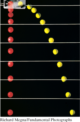
Figure
4-10 is a stroboscopic photograph of two golf balls, one simply released and the other shot horizontally by a spring. The golf
balls have the same vertical motion, both falling through the same vertical distance in the same interval of time.
The fact that one ball is moving horizontally while it is falling has no effect on its vertical motion; that is, the horizontal and vertical motions are independent of each other.
A Great Student Rouser
In Fig.
4-11, a blowgun G using a ball as a projectile is aimed directly at a can suspended from a magnet M. Just as the ball leaves the
blowgun, the can is released. If
g (the magnitude of the free-fall acceleration) were zero, the ball would follow the straight-line path shown in Fig.
4-11 and the can would float in place after the magnet released it. The ball would certainly hit the can. However,
g is
not zero, but the ball
still hits the can! As Fig.
4-11 shows, during the time of flight of the ball, both ball and can fall the same distance
h from their zero-
g locations. The harder the demonstrator blows, the greater is the ball's initial speed, the shorter the flight time, and the
smaller the value of
h.
At a certain instant, a fly ball has velocity  (the x axis is horizontal, the y axis is upward, and is in meters per second). Has the ball passed its highest point?
|
|
The Horizontal Motion
Now we are ready to analyze projectile motion, horizontally and vertically. We start with the horizontal motion. Because there
is
no acceleration in the horizontal direction, the horizontal component
vx of the projectile's velocity remains unchanged from its initial value
throughout the motion, as demonstrated in Fig.
4-12. At any time
t, the projectile's horizontal displacement

from an initial position
x0 is given by Eq.
2-15 with
a = 0, which we write as
Because

, this becomes
The Vertical Motion
The vertical motion is the motion we discussed in Module
2-5 for a particle in free fall. Most important is that the acceleration is constant. Thus, the equations of Table
2-1 apply, provided we substitute

for
a and switch to
y notation. Then, for example, Eq.
2-15 becomes
where the initial vertical velocity component
is replaced with the equivalent

. Similarly, Eqs.
2-11 and
2-16 become
and
As is illustrated in Fig.
4-9 and Eq.
4-23, the vertical velocity component behaves just as for a ball thrown vertically upward. It is directed upward initially, and
its magnitude steadily decreases to zero,
which marks the maximum height of the path. The vertical velocity component then reverses direction, and its magnitude becomes larger with time.
The Equation of the Path
We can find the equation of the projectile's path (its
trajectory) by eliminating time
t between Eqs.
4-21 and
4-22. Solving Eq.
4-21 for
t and substituting into Eq.
4-22, we obtain, after a little rearrangement,
This is the equation of the path shown in Fig.
4-9. In deriving it, for simplicity we let

and

in Eqs.
4-21 and
4-22, respectively. Because
g,
θ0, and
v0 are constants, Eq.
4-25 is of the form

, in which
a and
b are constants. This is the equation of a parabola, so the path is
parabolic.
The Horizontal Range
The
horizontal range R of the projectile is the
horizontal distance the projectile has traveled when it returns to its initial height (the height at which it is launched). To find
range
R, let us put

in Eq.
4-21 and

in Eq.
4-22, obtaining
and
Eliminating
t between these two equations yields
Using the identity

(see Appendix
E), we obtain
This equation does
not give the horizontal distance traveled by a projectile when the final height is not the launch height. Note that
R in Eq.
4-26 has its maximum value when

, which corresponds to

or

.
The horizontal range R is maximum for a launch angle of 45�.
|
However, when the launch and landing heights differ, as in many sports, a launch angle of 45� does not yield the maximum horizontal
distance.
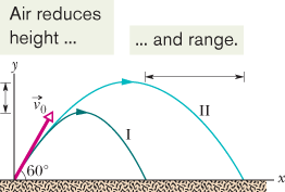
The Effects of the Air
We have assumed that the air through which the projectile moves has no effect on its motion. However, in many situations,
the disagreement between our calculations and the actual motion of the projectile can be large because the air resists (opposes)
the motion. Figure
4-13, for example, shows two paths for a fly ball that leaves the bat at an angle of 60� with the horizontal and an initial speed
of

. Path I (the baseball player's fly ball) is a calculated path that approximates normal conditions of play, in air. Path II
(the physics professor's fly ball) is the path the ball would follow in a vacuum.
|
|
| |
Path I (Air)
|
Path II (Vacuum)
|
|
Range
|
98.5 m
|
|
|
Maximum height
|
53.0 m
|
76.8 m
|
|
Time of flight
|
6.6 s
|
7.9 s
|
|
|
|
A fly ball is hit to the outfield. During its flight (ignore the effects of the air), what happens to its (a) horizontal and
(b) vertical components of velocity? What are the (c) horizontal and (d) vertical components of its acceleration during ascent,
during descent, and at the topmost point of its flight?
(a) vx constant; (b) vy initially positive, decreases to zero, and then becomes progressively more negative; (c)  throughout; (d)  throughout
|
|
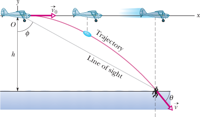
In Fig. 4-14, a rescue plane flies at  and constant height  toward a point directly over a victim, where a rescue capsule is to land.
| (a) |
What should be the angle  of the pilot's line of sight to the victim when the capsule release is made?
KEY IDEAS
Once released, the capsule is a projectile, so its horizontal and vertical motions can be considered separately (we need not
consider the actual curved path of the capsule).
Calculations:
In Fig. 4-14, we see that is given by
where x is the horizontal coordinate of the victim (and of the capsule when it hits the water) and . We should be able to find x with Eq. 4-21:
Here we know that because the origin is placed at the point of release. Because the capsule is released and not shot from the plane, its initial velocity is equal to the plane's velocity. Thus, we know also that the initial velocity has magnitude  and angle  (measured relative to the positive direction of the x axis). However, we do not know the time t the capsule takes to move from the plane to the victim.
To find t, we next consider the vertical motion and specifically Eq. 4-22:
Here the vertical displacement  of the capsule is  (the negative value indicates that the capsule moves downward). So,
Solving for t, we find  . Using that value in Eq. 4-28 yields
or
Then Eq. 4-27 gives us
|
| (b) |
As the capsule reaches the water, what is its velocity ?
KEY IDEAS
(1) The horizontal and vertical components of the capsule's velocity are independent. (2) Component vx does not change from its initial value because there is no horizontal acceleration. (3) Component vy changes from its initial value  because there is a vertical acceleration.
Calculations:
When the capsule reaches the water,
Using Eq. 4-23 and the capsule's time of fall , we also find that when the capsule reaches the water,
Thus, at the water
From Eq. 3-6, the magnitude and the angle of are
|
|
|
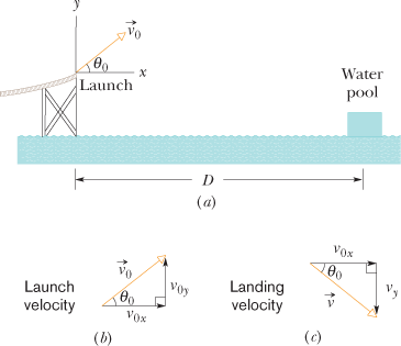
One of the most dramatic videos on the web (but entirely fictitious) supposedly shows a man sliding along a long water slide
and then being launched into the air to land in a water pool. Let's attach some reasonable numbers to such a flight to calculate
the velocity with which the man would have hit the water. Figure 4-15a indicates the launch and landing sites and includes a superimposed coordinate system with its origin conveniently located
at the launch site. From the video we take the horizontal flight distance as  , the flight time as  , and the launch angle as  . Find the magnitude of the velocity at launch and at landing.
KEY IDEAS
(1) For projectile motion, we can apply the equations for constant acceleration along the horizontal and vertical axes separately. (2) Throughout the flight, the vertical acceleration is  and the horizontal acceleration is .
Calculations:
In most projectile problems, the initial challenge is to figure out where to start. There is nothing wrong with trying out
various equations, to see if we can somehow get to the velocities. But here is a clue. Because we are going to apply the constant-acceleration
equations separately to the x and y motions, we should find the horizontal and vertical components of the velocities at launch and at landing. For each site,
we can then combine the velocity components to get the velocity.
Because we know the horizontal displacement , let's start with the horizontal motion. Since , we know that the horizontal velocity component vx is constant during the flight and thus is always equal to the horizontal component at launch. We can relate that component, the displacement , and the flight time with Eq. 2-15:
Substituting , this becomes Eq. 4-21. With  , we then write
That is a component of the launch velocity, but we need the magnitude of the full vector, as shown in Fig. 4-15b, where the components form the legs of a right triangle and the full vector forms the hypotenuse. We can then apply a trig
definition to find the magnitude of the full velocity at launch:
and so
Now let's go after the magnitude v of the landing velocity. We already know the horizontal component, which does not change from its initial value of  . To find the vertical component vy and because we know the elapsed time and the vertical acceleration  , let's rewrite Eq. 2-11 as
and then (from Fig. 4-15b) as
Substituting , this becomes Eq. 4-23. We can then write
Now that we know both components of the landing velocity, we use Eq. 3-6 to find the velocity magnitude:
|
|


 The Path of a Projectile

 Vertical vs. Horizontal Motion
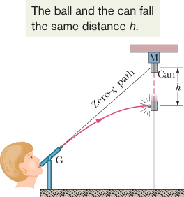
 Checkpoint 3


 Projectile dropped from airplane